Safety Services
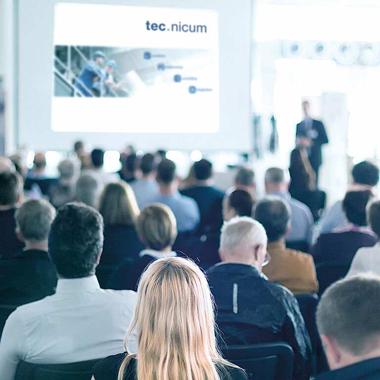
tec.nicum

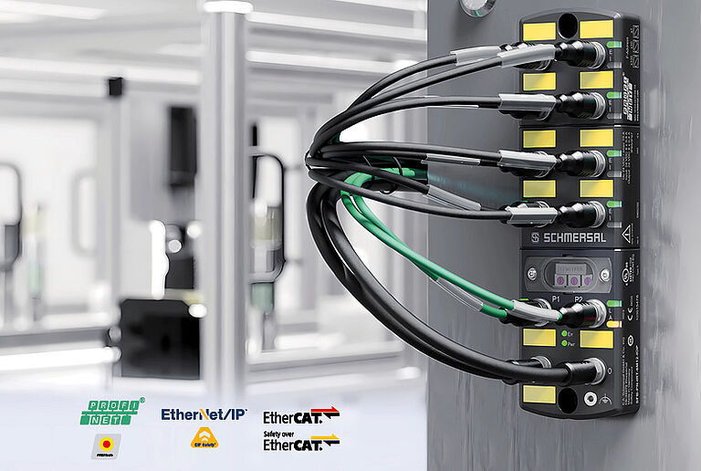
SAFETY SWITCHES AND SYSTEMS FOR YOUR
industry
OUR SERVICES
KNOW-HOW AND CONSULTANCY FOR MACHINE SAFETY
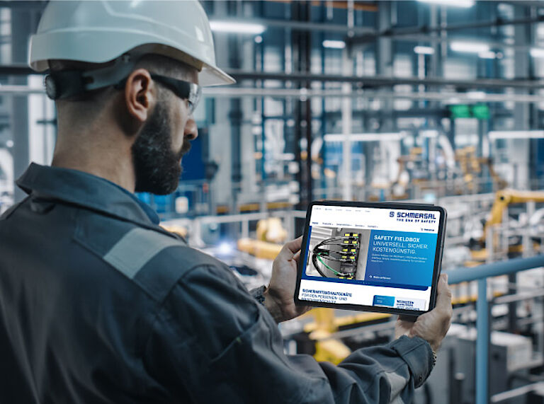
Schmersal regards itself not only as a developer and manufacturer of products and system solutions, but also as a consultant and service provider: tec.nicum is Schmersal's service division. tec.nicum offers competent, product- and manufacturer-neutral advice on all questions concerning machine safety and supports machine builders and machine operators in the standard-compliant design of their machines with its comprehensive Safety Services.
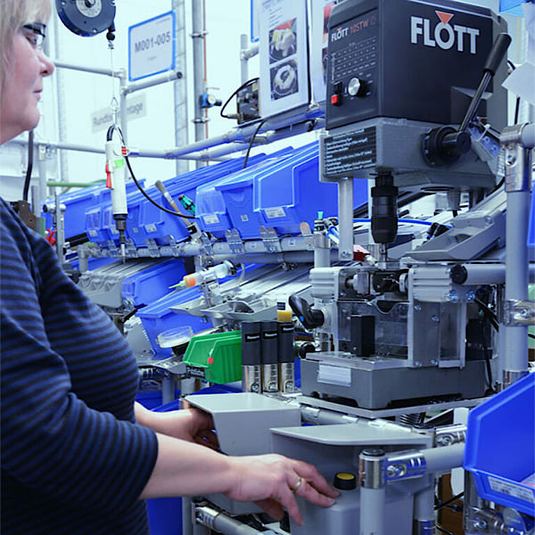
The specialists of the Schmersal service division also offer their know-how with regard to "lean production" and the ergonomic design of workplaces in manufacturing.
In our webinars, we provide information on the latest technical solutions for functional safety. In doing so, our specialists explain individual application possibilities in detail.


© 2026 K.A. Schmersal GmbH & Co. KG